Core Processing
Core Processing Form
If you are visiting the CSD Facility to process your own cores, or are sending cores for processing by the CSD Facility staff, please fill out both the Core Processing Form and email the Metadata Spreadsheet (XLS, 20KB) to CSDFacility@umn.edu.
Initial Core Description (ICD)
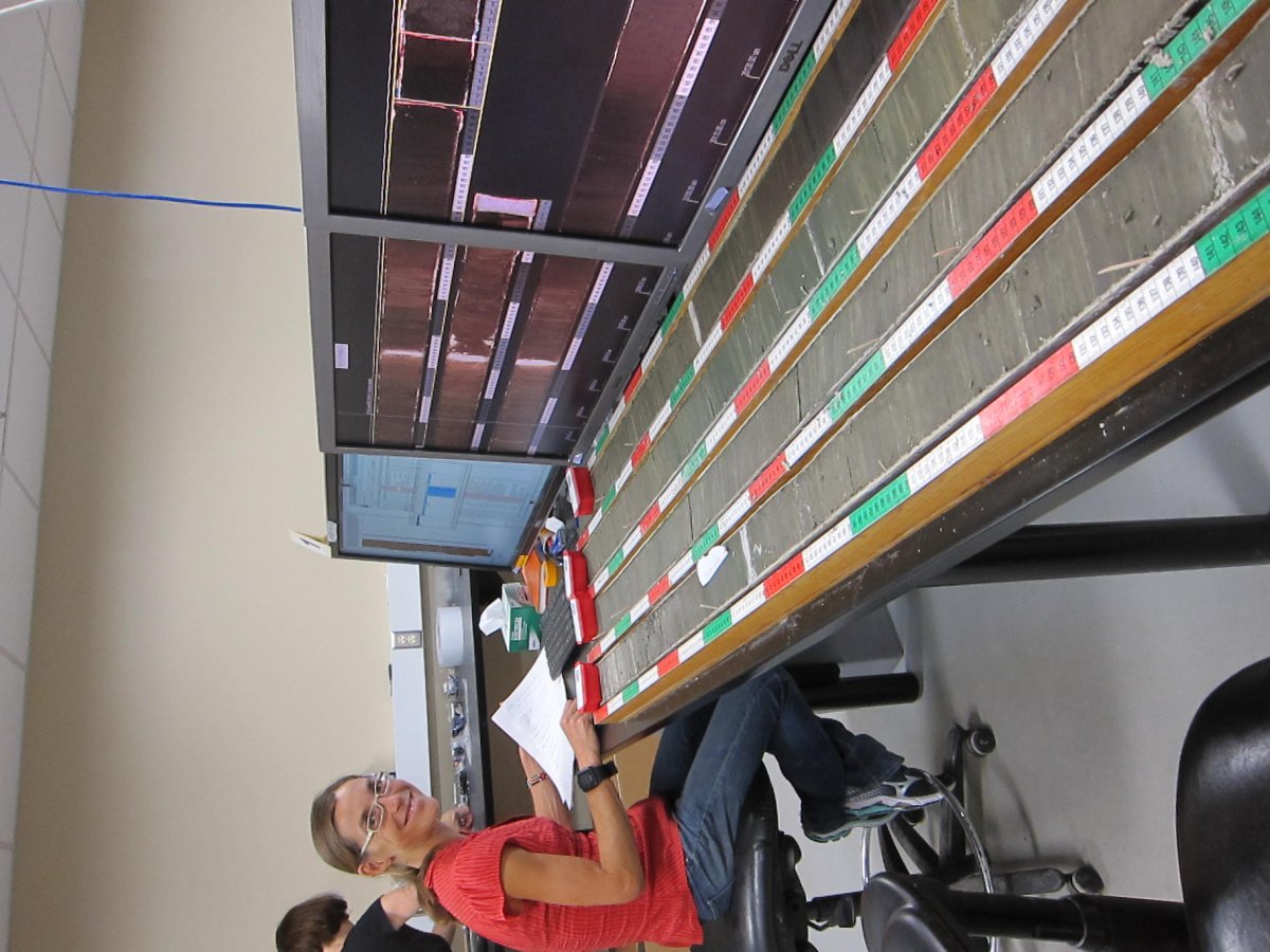
Initial core description (ICD) is the portion of core processing that precedes subsampling and analysis. Data collected during ICD, especially lithological and compositional information (i.e., core description and smear slides) form the basis and context for all further analyses, and often provide most of the interpretation of depositional environments and changes.
Core Splitting
Many cores are split or slabbed longitudinally into working and archive halves using a range of techniques depending on the type of liner and the core lithology. Subsequent splits can be made if needed, yielding quarter cores.
+
Soft Sediment
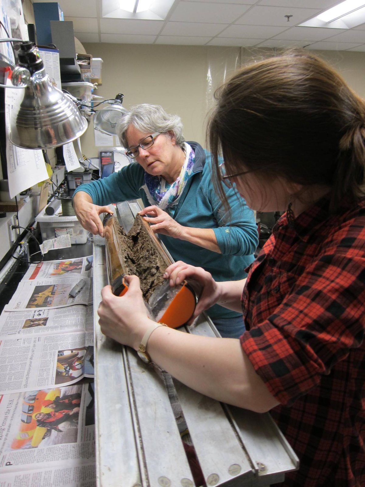
Soft sediment cores are split using techniques appropriate to the sediment and liner characteristics:
- Plastic core liners are scored using medical cast saws. The saw blades vibrate at high frequency and melt most of the way through the liner.
- Aluminum liners are cut using a table saw with aluminum cutting blade.
- After the liner is cut, the core is moved to a core splitting table with a slot through the middle that allows tools to access both top and bottom liner cuts.
- The cut is finished through plastic core liners using a utility knife.
- The appropriate tool for splitting the sediment is determined by the water content and the lithology. The sediment is cut using large metal blades (upper ~3 to 5 m with the highest water content), abrasion-resistant thread (Spectra fiber fishing line or similar), or a serrated knife (peat or other fibrous material).
- If the sediment shatters rather than yielding to a clean cut, other core splitting techniques are required (band saw or rock saw; see below).
- The split core face is scraped clean.
+
Peat
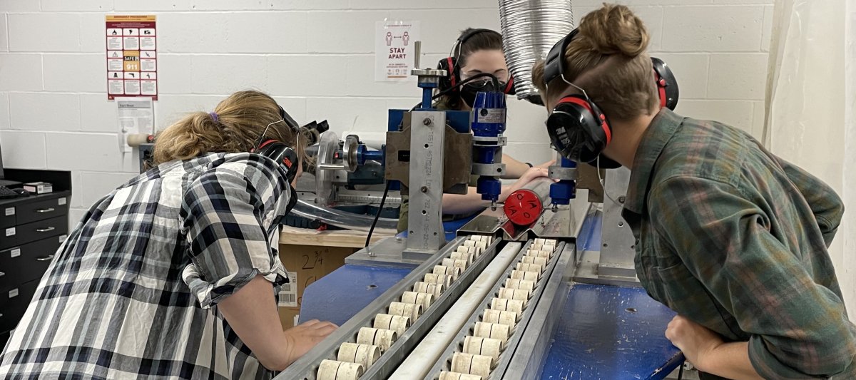
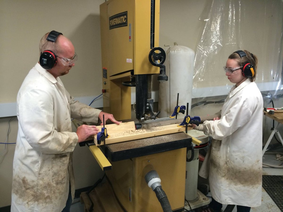
Peat cores with fibrous pieces of vegetation or large chunks of wood can sometimes be split with a serrated knife if the fibrous material is sufficiently decomposed. Otherwise, best results are obtained using a band saw with a segmented diamond grit blade. This technique smears sediment on the core surface, which must be aggressively scraped clean after splitting.
+
Rock and Other Lithified Cores
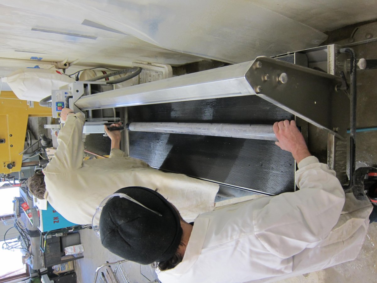
Core Scanning
+
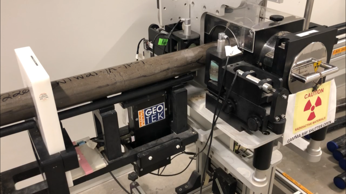
Geotek MSCL-S
Whole core (preferred) or split core logs with the Geotek Standard Multisensor Core Logger (MSCL-S) for:
- Magnetic susceptibility (loop)
- Gamma density
- P-wave velocity and amplitude
- Natural gamma radiation
- Electrical resistivity
+
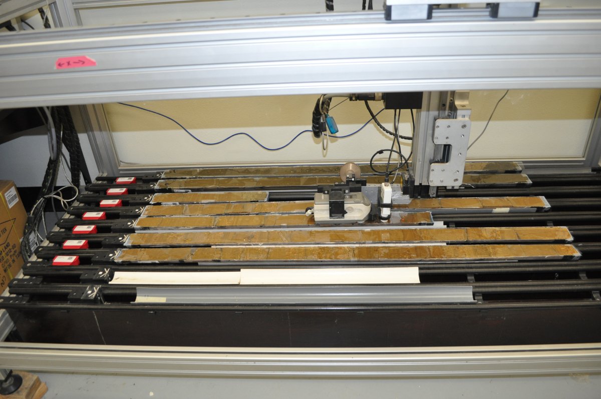
Geotek MSCL-XYZ
Sequential automated logs of up to 9 split cores with the Geotek XYZ Multisensor Core Logger (MSCL-XYZ) for:
- Magnetic susceptibility (high-resolution point sensor)
- Color reflectance spectrophotometry
+
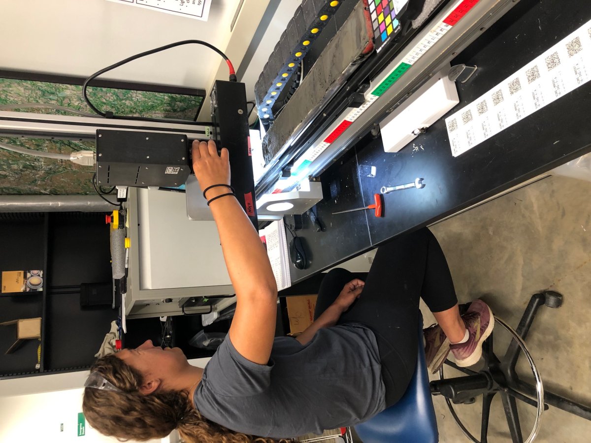
Digital Linescan Core Imaging
High resolution cores images are collected using the Geotek Core Imaging System (CIS). The camera is set up with with cross-polarized filters on the light source and lens to remove glare from the core face. Resolutions of 25, 50, and 100 micron (40, 20, and 10 pixels/mm) are possible.
Cores are imaged with a color card that contains 18 calibrated color patches and 6 calibrated grayscale patches. Images may be adjusted to the known color values of the patches; thus near-perfect color rendition may be obtained.

+
X-Ray Fluorescence (XRF)
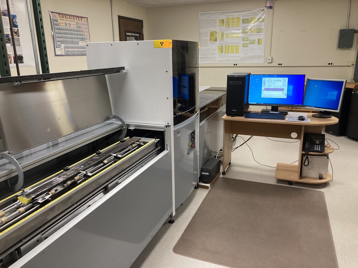
The Large Lakes Observatory at the University of Minnesota-Duluth campus hosts the CSD Facility XRF Core Scanning Facility. This lab provides ITRAX elemental and X-radiographic core scans for the research community. Cores are commonly first processed at the main CSD Facility lab in the Twin Cities and are then transferred in batches by facility staff to/from the XRF Lab in Duluth for the much slower scans on the ITRAX instrument. Data services and archiving are integrated with all other data generated at the CSD Facility.
Lithologic Description
+
Visual Core Description
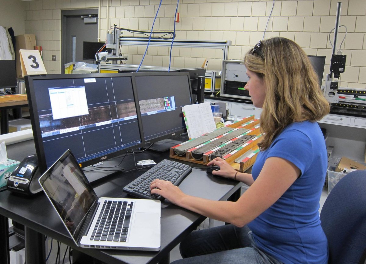
Macroscopic description of core lithology, texture, structure, color, bedding, fossils, coring/drilling artifacts, and other features.
+
Microscopic Description
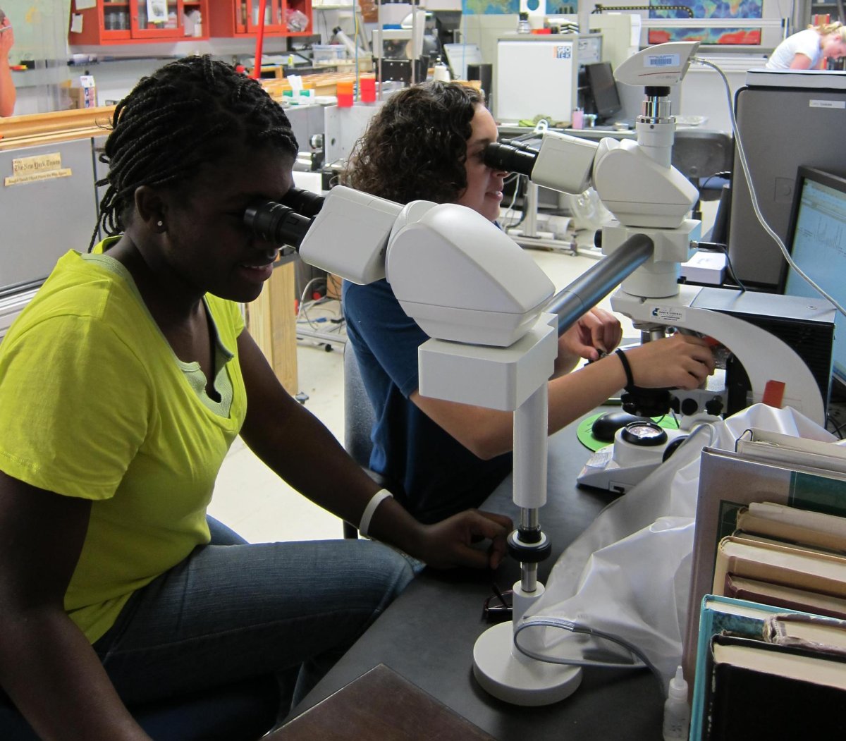
Microscopic description of core lithology, mineralogy, clastic grain size, floral and faunal remains, diagenetic features, and other characteristics is accomplished through petrographic inspection of smear slides (soft sediment cores) and thin sections (rock cores and lithified materials). Smear slides are a simple, cheap, and powerful tool for the characterization of unconsolidated sediment, providing a tremendous amount of information about past depositional environments. Tool for Microscopic Identification (TMI) is an online tagged database of sedimentary components in petrographic and reflected light microscope view with tutorials on identification and interpretation.
+
Stratigraphic Correlation and Composite Splicing
In soft sediments, complete core recovery is rarely obtained in a single borehole due to gaps/core loss and deformation caused by the coring process. Construction of a complete stratigraphic profile, called a composite splice, is performed through combining representative stratigraphic intervals cored in two or more holes at the same site, and assignment of a composite depth scale.
