Hydraulic Fracturing
It is rare that a geoengineering process reaches such heights of popular interest that it is even written about in Vanity Fair, but the topic of hydraulic fracturing has reached that level of cultural impact (see Vanity Fair, June 21, 2010). Hydraulic fracturing comes up frequently in the context of producing oil and gas from previously unproductive shale reservoirs. In Minnesota, we hear a lot about the oil fields in North Dakota and the related sand mining in southeastern Minnesota. However, it is not widely known that hydraulic fracturing has been studied and refined at the University of Minnesota since the 1960s. And that research is still going strong as researchers continue to develop the processes and uses of hydraulic fracturing, related technologies, and methods for practicing hydraulic fracturing in sustainable ways.
The earliest documented application of hydraulic fracturing might be T. L. Watson’s 1910 description of induced “sheeting” in granite quarrying operations. Hydraulic fracturing was used to “cleave” granite during quarrying to create smooth sheets of mined rock. Watson (1910) described how compressed air injected into a lift-hole was capable of cleaving (fracturing) the rock a distance of more than 70 meters (roughly 230 feet) from the lift-hole. Another early mention of hydraulic fracturing is contained in a 1935 paper by Grebe and Stoesser that was published in World Petroleum (August 1935): “In the experiments on treating wells…, it was discovered that a fluid pressure at the bottom of the well sufficient to counter-balance the weight of the rock above it plus an additional pressure required for actually breaking (cracking) the formation, makes possible the introduction of fluids into new crevices thus created.”
In 1949, the term “hydrafrac process” was introduced in a paper written by J.B. Clark, who together with F.R. Farris, both from Stanolind Oil and Gas Corporation, conceived the idea of hydraulically fracturing a rock formation to enhance production from oil and gas wells. Theoretical analyses soon followed (Hubbert and Willis 1957; Perkins and Kern 1961) and set the foundation for modeling the shape of a hydraulic fracture system in two dimensions.
It was the possibility of using hydraulic fracturing to measure stress in underground rock formations that spurred the development in relation to the fracturing process. This is the point where the University of Minnesota (UMN) became deeply involved in hydraulic fracturing research.
In 1966, the US Army Corps of Engineers asked Professor Charles Fairhurst of UMN to design and build equipment capable of determining the state of stress in rock at depths of several hundred meters. After careful study of various possibilities, hydraulic fracturing—where the fluid pressure developed during fracture (or opening of existing fractures) of the rock around the borehole could be interpreted in terms of the pre-existing stress field in the rock mass—was determined to be the most promising procedure. Several UMN students, who are now world leaders in the field, wrote dissertations on issues related to hydraulic fracturing, from theoretical analysis and laboratory experiments, to small- and full-scale field testing, to rock fracture modeling and solid-fluid coupling effects (Haimson 1968; Von Schoenfeldt 1970; Hardy 1973; Roegiers 1974; Cornet 1975; Leonard 1985).
In 1993, Professor Emmanuel Detournay arrived at the Department of Civil Engineering at UMN and brought new life to the study of hydraulic fracturing. Detournay directs a comprehensive research program aimed at developing rigorous reference solutions and robust numerical methods for the coupled rock-fluid process.
Two hallmarks of this research activity are (i) the construction of multi-scale tip asymptotics for fluid-driven fractures and (ii) the parametric organization of reference solutions for plane or radial fracture geometries using scaling analysis. Many of Detournay’s Ph.D. students are contributing to the industry (Carbonell 1996; Garagash 1998; Savitski 2000; Adachi 2001; Bunger 2005; Kovalyshen 2010).
Research topics related to hydraulic fracturing have grown. Professors Roberto Ballarini, Jia-Liang Le, Sofia Mogilevskaya, and Vaughan Voller study sophisticated analytical and numerical models for fracture propagation.
Professors Stefano Gonella, Bojan Guzina, and Joseph Labuz study the critical aspect of monitoring crack growth in the process of hydraulic fracturing. As a rock fractures, energy is released in the form of stress waves that travel through the rock. These stress waves can be used to map the growth of a fracture. The vision of this group of researchers is to transform hydraulic fracturing into a controllable process for responsible and efficient harvesting of resources. Computational algorithms and software are being developed to provide mechanically rigorous and statistically meaningful predictions of subsurface fractures. Seismic imaging techniques are being formulated to track the propagation and characteristics of fractures in 3D and real time.
Hydraulic fracturing is being applied to wider and wider areas and in situations where there is little prior experience, so a deep understanding of the fracture process in rock is imperative. The geoengineers at UMN are developing that understanding and preparing future researchers to carry this work forward.
How Hydraulic Fracturing Works
Hydraulic fracturing is an engineering process that involves aspects of chemistry, fluid mechanics, and rock mechanics. Stated simply, hydraulic fracturing is a prcess by which fluid is pumped underground at sufficient rates and pressures to break rock formations. A fracture is generated in a rock by increasing the fluid pressure until a crack extends away from the point where the fluid is being injected. This process is now used extensively to break rock underground to help free oil or gas trapped in the rock formations (see Figure 1).
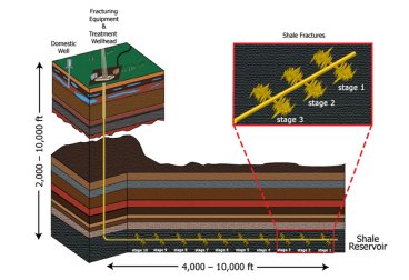
staged hydraulic fracture treatment (Induced Seismicity
Potential in Energy Technologies, The National
Academies Press, Washington D.C. 2013)
A typical hydraulic fracturing process involves drilling a vertical borehole into the ground to the top of an oil or gas bearing rock formation and placing a steel casing in the hole. The hole is then sealed using cement slurry, which is pumped thrugh the casing until it flows around the outside of the casing back to the surface. Once the seal is formed, a hole or wellbore is drilled through the oil or gas formation.
When a fluid is injected down the wellbore, pressure builds in the rock until it breaks (or existing fractures open). The width, direction, and length of cracks depend on the stress field, material properties, and fluid coupling. Cracking—or fracturing—is also influenced by the porosity, permeability, and natural fracture pattern of the rock formation. Following the initial “breakdown” of the rock formation, various fluids and rates of injection are used to extend the fractures. Sand or other material is needed to keep the fractures from closing when the pressure from the injected liquid is released.
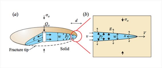
Flow of fluid in the created fractures is governed by classical Reynolds fluid flow equations. The pressure drop along a fracture depends on the viscosity of the fluid used to create the fracture and the permeability of the rock, which could lead to the fluid leaking off. The size of the fracture aperture depends on the stiffness of the rock mass and the distribution of fluid pressure along the crack. Extension of the fracture depends on the mechanical energy supplied to the region around the crack tip. The crack tip may propagate ahead of the fluid, leading to a lag—a dry region between the fluid front and the tip of the resulting crack. Figure 2 illustrates the classical radial fracture model, in which it is assumed that the fracture propagates symmetrically away from the borehole in a plane normal to the minimum (least compressive) principal in-situ stress, σo.
Geoengineers at UMN seek to understand the behavior of rock and fluid in order to predict the hydraulic fracturing process and use it productively and sustainably.